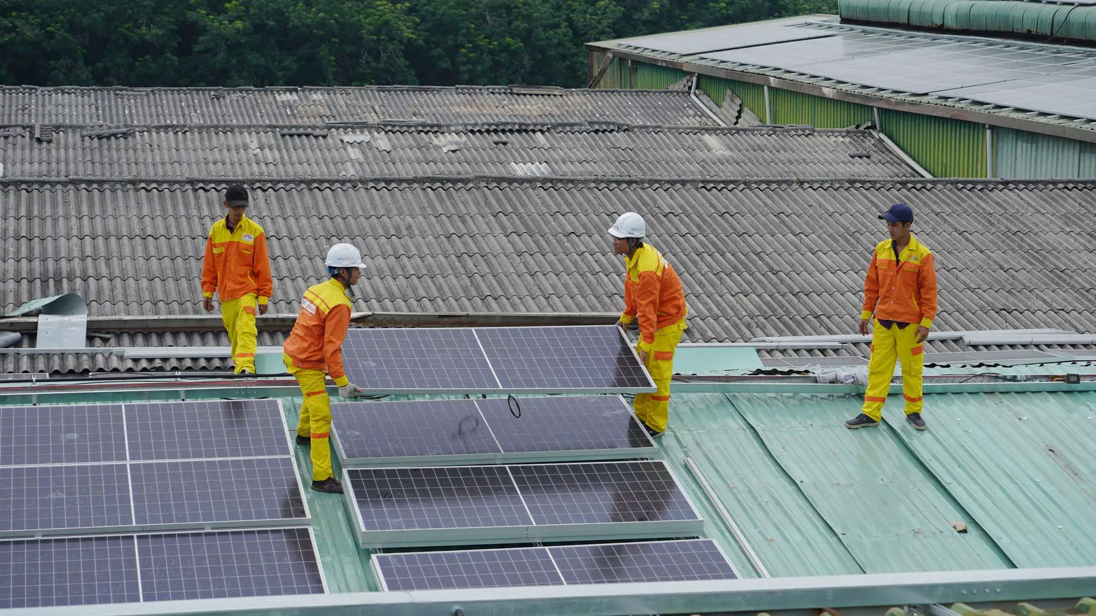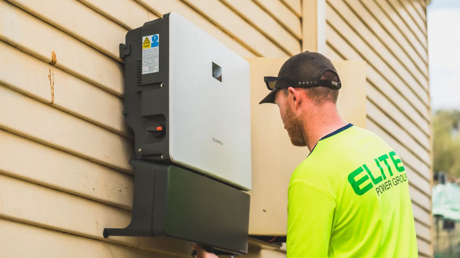
Low output in TOPCon installations usually stems from soiling, shading, or electrical faults. This guide lists common symptoms and fixes to help you restore performance and prevent future efficiency loss in monocrystalline panels.
- Low output often begins with simple issues like soiling or partial shading rather than internal cell defects.
- Compare inverter data against expected baseline values to isolate underperforming strings quickly.
- Regular visual inspection and electrical testing can catch hidden faults before they reduce long-term yield.
Why TOPCon Panels Produce Less Than Expected
TOPCon cells use a tunnel oxide passivated contact structure that improves carrier collection and reduces recombination. This design supports higher efficiency than older architectures, but it does not make the module immune to environmental and electrical stress. When a site reports low output, the first task is to determine whether the loss is site-specific or panel-specific.
Site issues affect the whole array. Panel issues affect a specific module or string. The distinction matters because the fix is different. A dirty soiling layer on a rooftop in a dusty region will drop output across multiple strings. A cracked busbar or a degraded solder joint will pull down only one module. Understanding this separation prevents wasted effort. If you spend hours swapping modules when the real cause is a layer of pollen on the glass, you have not solved the problem. You have only delayed it.
TOPCon panels are also sensitive to moisture ingress over time. The tunnel oxide layer helps passivation, but if the encapsulant or frame seal fails, water can reach the back contact. This creates a slow degradation path that shows up as a rising shunt resistance or a dropping open-circuit voltage. Unlike visible cracks that appear immediately after hail, this kind of failure is insidious. It works quietly in the background until the string output drops enough to trigger a complaint.
Another factor is the temperature coefficient. TOPCon cells generally perform better at high temperatures than older polycrystalline or early mono-crystalline technologies. However, if the cooling air flow is restricted, or if the mounting system traps heat, the temperature coefficient can work against you. In a flat-lying array, air circulation is often poor. In a steep-angled roof, it is better, but still dependent on wind speed. If the panels are operating above their optimal temperature range, the output will drop even if the irradiance is high.
How to Isolate the Source of the Drop
Start with the inverter. Pull the last 24 to 48 hours of production data and compare it against the same period last year, or against the site baseline if the system is new. Look for a sudden step change or a gradual decline. A sudden drop points to a physical event such as snow, hail, a fallen branch, or an inverter fault. A gradual decline suggests soiling, vegetation growth, or module degradation over time.
Check the string currents next. If the inverter supports per-string monitoring, compare each string against the others. One string reading 10 to 15 percent below the rest indicates a localized problem. If all strings are low, the issue is likely environmental or inverter-related. If the monitoring system only shows total array current, you may need to use a clamp meter on the DC cables to isolate the strings manually. This is more labor-intensive but often necessary in smaller systems.
Look at the inverter log for fault codes. A persistent “low voltage” or “AC undervoltage” error suggests a mismatch between the inverter and the module output. This can happen if the string voltage is below the inverter’s minimum operating point, especially in winter or when the sun is low. If the inverter is going into maximum power point tracking (MPPT) limits, it may be clamping the output at a lower level than the modules can produce.
Do not ignore the date and time of the drop. If the drop happens only when the inverter wakes up in the morning, check the startup threshold. If it happens during peak sun hours, look at the physical array. If it happens in the evening, check the low-light performance and the inverter’s shutdown curve.
Common Symptoms, Likely Causes, and Fixes
The table below lists the most frequent causes of low output in TOPCon installations. Use it as a first-pass checklist when a site reports underperformance.
| Symptom | Likely cause | What to do |
|---|---|---|
| Whole array output below expected | Soiling, snow, or seasonal shading | Clean panels, remove snow, trim vegetation, and verify inverter settings |
| One string significantly lower than others | Partial shading, a failed bypass diode, or a faulty module | Inspect the string for shade, check bypass diode status, and swap the weak module if needed |
| Output drops only in the morning or late afternoon | Inverter threshold settings or low-light performance | Review inverter startup threshold and verify panel low-light characteristics match the site |
| Intermittent loss across multiple strings | Loose MC4 connectors or a ground fault | Inspect connectors for corrosion or looseness, check ground continuity, and retorque terminals |
| Gradual decline over months | Module degradation, busbar oxidation, or solder fatigue | Perform an electrical inspection, check for hot spots with thermal imaging, and replace affected modules |
Checking Electrical Integrity
TOPCon modules have the same basic electrical architecture as other crystalline panels, but their passivated contacts can be more sensitive to moisture ingress over time. A small pinhole in the encapsulant can allow water to reach the back contact. This creates a slow degradation path that shows up as a rising shunt resistance or a dropping open-circuit voltage.
Run a visual check first. Look for discoloration near the edges, bubbles in the encapsulant, or discoloration on the backsheet. Bubbles often indicate that moisture has trapped in the layer. If you see white or yellowish spots on the front glass, it may be a sign of delamination or a failed seal. These are not always visible from a distance. You may need to get close to the panel to see the damage.
Then use an electrical tester to measure open-circuit voltage and short-circuit current on the affected strings. Compare the readings to the nameplate values and the other strings. A drop in open-circuit voltage that is not explained by temperature or soiling suggests an internal electrical fault. If the short-circuit current is low, it may indicate a cracked cell or a damaged busbar. If the open-circuit voltage is low but the short-circuit current is normal, it may be a bypass diode failure or a partial short.
If you have access to thermal imaging, scan the module at peak load. A small hot spot on a solder joint or a bypass diode is a warning sign. The joint may still conduct, but it is losing efficiency. Catching it early prevents a complete open circuit later. Thermal imaging is particularly useful for detecting bypass diode failures. When a bypass diode fails, the current bypasses it, and the diode heats up. If you do not catch it, the diode can fail open, and the entire string may drop out.
Inspecting Mechanical and Environmental Factors
Physical damage is a common cause of underperformance, especially on rooftop and ground-mounted systems. Hail, wind uplift, and foot traffic can crack the glass or delaminate the encapsulant. Cracks that cross a cell can split the parallel circuit and reduce output. Even a small crack can reduce the effective area of the cell and lower the output.
Check the mounting hardware. Loose clamps allow the panel to vibrate in wind. Vibration fatigues the solder joints and the busbar. Tighten clamps to the manufacturer specification and inspect for cracked or corroded fasteners. On ground-mounted systems, check the ballast or ballast plates. If the structure is not level, water can pool on the panel surface and create uneven soiling. Pooled water can also cause localized heating and accelerate degradation.
Vegetation is often overlooked. Grass, vines, or tree branches can shade the bottom of a panel. Even a small shaded area can reduce the string output because the series-connected cells limit the current. Trim vegetation to the manufacturer recommended clearance and recheck after each season. In dense vegetation, you may need to trim more frequently than you think. A single leaf can shade a cell and reduce the output of the entire string.
Also check for animal damage. Birds can scratch the glass or leave droppings that are highly acidic. Squirrels and other animals can chew on cables and damage the wiring. Inspect the perimeter of the array for signs of animal activity. If you find damaged cables, replace them immediately. Animal damage can also create a fire risk.
Prevention Tips for Long-Term Performance
Prevention is cheaper than repair. Set up a baseline in the first 30 days of operation. Record the expected output for the site and use it as a reference for future comparisons. A small drop of 2 to 3 percent may be normal seasonal variation. A drop of 10 percent or more warrants investigation. Keep a simple spreadsheet or use your monitoring software to track the output over time. This data will help you spot trends before they become problems.
Clean the panels on a schedule that matches the local environment. In dusty areas, quarterly cleaning is typical. In coastal areas, rinse the panels to remove salt residue. Do not use harsh chemicals. Use plain water and a soft brush. Harsh chemicals can damage the anti-reflective coating and reduce the efficiency of the panel. If you have a lot of dust, consider a waterless cleaning system. These systems use a microfiber cloth and a specialized solution that lifts the dust without water. They are less effective on heavy soiling but can be a good option for small systems.
Review the inverter settings annually. Startup threshold, maximum power point tracking range, and communication settings can drift. A misconfigured inverter will not report the full available power. Have a qualified technician verify the settings against the manufacturer documentation. Also check the firmware. Inverters often receive firmware updates that improve performance or fix bugs. Make sure your inverter is up to date.
When to Call a Professional
Some faults are not safe to diagnose without specialized equipment. If a module shows signs of fire damage, if there is a persistent ground fault, or if the inverter reports a fault code that you cannot clear, stop working and call a qualified installer. Do not open the module housing. TOPCon cells are not fragile, but the back contact and passivation layer are sensitive to moisture and mechanical stress. A professional can use an I-V curve tracer to identify the exact failure mode and decide whether the module should be replaced.
If you suspect a ground fault, use a multimeter to check the resistance between the module frame and the ground. A low resistance indicates a ground fault. This is a safety hazard and should be addressed immediately. A ground fault can cause a fire or an electrocution risk. Do not ignore it.
Also call a professional if you see signs of delamination or bubbling in the encapsulant. These are signs of internal moisture damage. The module may still work, but it is likely to fail soon. Replacing it now is cheaper than replacing it later when it fails completely.
Final Checks Before You Close the Investigation
Before you declare the issue fixed, run a final verification. Confirm that the string currents are back within the expected range. Check the inverter for any new fault codes. Take a photograph of the repaired area for your records. If you replaced a module, note the serial number and the date of replacement. This documentation is important for warranty claims and for future maintenance.
Low output in TOPCon systems is rarely a mystery. Most cases trace back to soiling, shading, or a loose connection. The key is to follow the data, check the physical installation, and test the electrical integrity. A structured approach saves time and prevents a small issue from becoming a costly one. Always document your findings and actions. This will help you and future technicians understand what happened and what was done to fix it.
Frequently asked questions
Does TOPCon panel efficiency loss happen faster than PERC?
No. TOPCon cells use a passivated contact design that reduces recombination, which generally supports longer-term stability. Efficiency loss is usually driven by soiling, mechanical damage, or environmental stress, not by the cell architecture alone.
Can partial shading on a single cell reduce the whole string output?
Yes. In a series-connected string, the lowest performing cell limits the current for the entire string. Even a small shaded area can pull down the string output, especially if the bypass diode does not activate.
How often should I check my TOPCon panels?
A quick visual check every 3 to 6 months is a good baseline. In dusty or high-debris areas, check more often. Use a thermal camera during peak production to spot hot spots before they become failures.
Is it safe to clean TOPCon panels with a pressure washer?
Use caution. High-pressure water can force moisture into the panel edges or damage the encapsulant. Use a low-pressure spray and a soft brush. Avoid directing the stream at the frame or junction box.
Can a faulty inverter cause low output in a healthy array?
Yes. If the inverter is underpowered, misconfigured, or failing, it will not track the maximum power point correctly. This results in lower output even when the panels are clean and unshaded. Check the inverter settings and replace it if the fault persists.